A.Jurchevsky « The sportsman - submariner » Release 6, 1964
The hydraulic gun
In foreign press is informed on a new underwater gun - hydraulic gun. Though it is poorly applicable in our seas and lakes, that on defeat, a large fish and large sea predators, nevertheless represents doubtless interest.
The basic details of a gun is the following (fig. 1): 1) barrel with located on it details; 2) trigger system; 3) trigger hook; 4) air rubber bag with a high-pressure tank; 5) a hydraulic pump; 6) air pump for a bag; 7) manometer for the control of pressure over a bag.
Fig.2. Details of a gun: 1 - rubber bag; 2 - high-pressure tank; 3 - grid; 4 - barrel; 5 - cartridge of change of force of fight.
The principle of action of a gun consists in the following. In the reinforced rubber bag 1 (fig. 2) located in a high-pressure tank 2, through the union is pumped up air under pressure 20 - 25 atmospheres. It is done once at assembly of a gun at a factory or it is made independently at disassembly and assembly of a gun. The rubber bag is stretched by this pressure and borrows all cavity of a high-pressure tank limited to a grid 3.
Diameters of apertures of a grid are picked up such that durability of a bag was not broken at cave-in of an environment in apertures of a grid. Loading of a gun is better for carrying out in water. At a ramming of a spear shaft all volume of water through the trigger system will act in a high-pressure tank. Further, the hydraulic pump located from above, pumps up water in a high-pressure tank. Pressure of water in a cylinder raises. The air bag thus will be compressed, and pressure of air in it to raise. The hydraulic pump allows to create pressure of water in a cylinder (and so, and air in a bag) up to 120 - 130 atmospheres. The gun is loading.
Work trigger system.
After a forcing of water in the chamber of the hydroaccumulator all system will be under pressure. In the chamber A of water equally also to pressure in the hydroaccumulator. Water will pass through apertures and fill B.
Under action of a spring, and also from pressure of water upon an internal end face of a conic valve 5 and on his internal end face which is taking place in the chamber, a conic valve 5 and a saddle 7 will be closed (fig. 3, а). The output of water in a barrel will be closed.
By pressing a trigger hook 8 last, having turned on an axis 1, will press the top end a conic rod 4 and, having overcome force of a spring 6, will move it. Thus apertures in a conic rod 4 will be blocked also water from the chamber A of can act in the chamber B. At the same time the conic rod 4 will leave from an sealing "O" rings 3 and in the chamber B because of the formed backlash between a conic rod and an sealing "O" rings pressure will fall up to pressure of surrounding water.
At reduction of pressure in chamber B the force working on an external end face of a cone, and a cone pressure inside chamber A saddle 7 decreases pushes away, having opened access to water in barrel which pushes out a spear shaft. During the initial moment pressure of water upon a spear shaft will be approximately equal to pressure in a cylinder, i.e. 120 atmospheres. In process of expansion of a bag pressure upon a spear shaft falls. Pressure at the moment of a start of a spear shaft depends on volume barrel and volume of the water pumped up in a cylinder. In a described design volume of water in a cylinder about 80 sm3.
Pressure upon a start of a spear shaft of 45 atmospheres.
At initial pressure in a cylinder of 145 atmospheres. Pressure of water upon a spear shaft before a shot can be reduced twice. For this purpose on barrel 4 (see fig. 2) is apertures for an output of water. These apertures are closed by the cartridge 5. If necessary to reduce force of impact twice the cartridge 5 turns, opening an additional output to water at the moment of a shot. It is necessary to note, that the spear shaft can serve as the piston for loading water through barrel and a trigger system. The spear shaft will consist of two tips and an emphasis for loading.
Fig.3. Position a trigger system:
a - up to a shot; b - at the moment of a shot.
1 - an axis of a trigger hook; 2 - chamber of a high pressure; 3 - sealing "O" rings; 4 - conic rod; 5 - conic valve; 6 - spring; 7 - saddle; 8 - trigger hook.
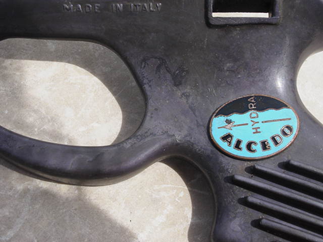
Yes, that is the Alcedo "Hydra", it was invented by the Italian, Carlo Alinari.
The initial versions do not have the pump on the top that serves as a
surcompressor. On the surcompressor body there is a table indicating what I
think are five strokes of the hydropump, it is printed on an anodised aluminium
badge riveted onto the side of the pump.
The label on the badge says "NON SUPERARE POMPATE", one column says "FRECCIA" ,
then 1, 2, 3, 4, 5 and the adjacent column says "SURC.", then says 40, 30, 20,
10, 0. The pump I have is jammed shut and has resisted years of me trying to
get it to move with heat, cold, WD40 (entire can!), penetrating oil, high
frequency vibration, impact blows, differential thermal expansion of various
parts, but to no avail. I am certain the problem is aluminium oxide build-up
inside the pump, I found this oxide under the rear removable cap of the pump and
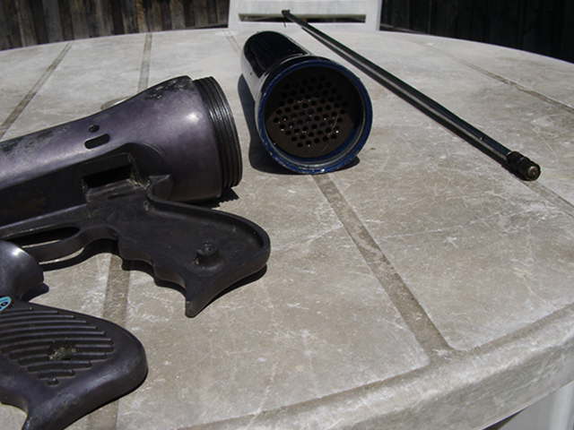
it is certain to be the same inside the pump. The rest of the gun is OK as
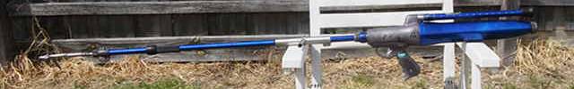
internal parts are very simple, but gun is very heavy, almost ridiculous in its
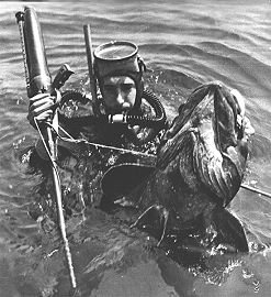
weight. A speargun for scuba divers I think rather than freedivers. Attached
is one of the few photos that I found, this one with a happy scuba diver having
shot a fish with one.
I believe Carlo Alinari was later involved with the "SOS" company, they
manufactured a rear handle hydropneumatic gun, but I only ever saw one at a dive
equipment show. I should have bought it, the year was 1976 and the gun not much
more than $100, which seemed a lot of money back then! The distributor did not
know how it worked, but said the gun seemed weak, he did not realise that it had
to be filled with water before inserting the spear. The SOS speargun was there
as a curiosity, they were selling scuba related equipment, so knew little about
the gun. They represented "Scubapro", an American company that also sold SOS
equipment such as depth gauges and decompression meters, but with "Scubapro"
labels stuck on them!
This article has been published in 1964. I have read this in 1984 and already
in 1985 have made the hydropneumatic speargun.
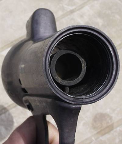
The barrel bore of the "Hydra" is slightly greater than 12 mm, or 0.5 inch, I
measured it with vernier callipers at the muzzle end. The big rubber seal in
the barrel base makes measurement of the barrel bore difficult at that end as
the rubber seal has been slightly extruded into the barrel.
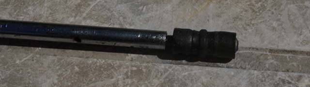
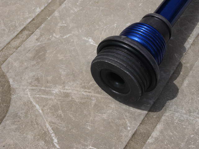
More photos, including the spear tail. It has two seals, one acts as a
ring-type seal and the other a cup-type seal at the extreme tail. I doubt that
replacement rubber seals would be available today, they appear to have been made
for this gun or something very similar at the time of the Hydra's manufacture.
The rubber seals are mounted on a metal body that screws into the rear of the
spear shaft. The spear shaft is tapered at the rear end for about the last
third of its length, however I have not measured it exactly. The spear shaft is
chrome-plated steel.
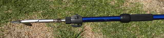
The spear tip is a cast "Mako" tip made in Australia, the
original owner has converted the spear to the breakaway-tip type, you can see
the connecting cable in one photo. The line slide is missing.
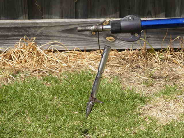
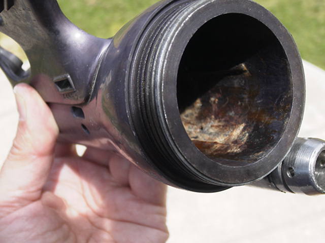
The rear of the gun has no threaded connection for a hand pump, it only has an
angled circular lip which must be gripped by some expanding jaw type arrangement
as the lip is angled inwards when looking at it from the rear. I have never
seen the hand pump for a "Hydra", except for that fuzzy web-site photo. Some
people have said to me that they were supplied without a pump! I doubt that the
internal air pressures used were as described in that Russian/Ukrainian language
article on the Alcedo "Hydra" which you sent to me recently, I think the "Hydra"
used lower air pressures. This is because the rubber bladder could extrude
through the many holes in the metal grille, however the grille (or vented plate)
is very thick in cross-section, maybe four or five millimetres thick, but hard
to measure accurately. If I shake the rear tank then I can hear the rubber
bladder flopping around inside the tank, so I assume that it has little or no
air pressure inside it at the moment.
The vented plate or grille is much thicker than I first thought it was. I made
a very small plastic hook to pass through the holes and catch on the other side
of the plate. I now estimate the vented plate is approximately 12 mm in
thickness and it looks to be made from steel, it is a rusty brown colour, but it
is silvery where it has been scratched when someone else tried to undo it. It
has 61 vent holes arranged in a hexagonal pattern, each vent hole is 4 mm in
diameter. Each side of the hexagon has 5 holes, across the centre line there
are 9 holes. The vented plate appears to be screwed into the rear tank, but it
is very tight and I have never had any success in getting it to loosen and turn
in order to remove it. Quite a bit of old grease lining each of the holes, I
found traces of it each time I pushed the plastic hook through the holes in
order to try and catch its tip on the other side of the plate. This was easier
to do in the peripheral holes as the central holes have the rubber bladder
pushing up against them. I think any resistance of the bladder is due to the
thickness of the rubber rather than it containing any air pressure.
Spear of Alcedo "Hydra" is 10 mm diameter, it only tapers down to 8 mm diameter
at the rear end. The shaft's tail seals are intended to be replaced as a single
unit as the two rubber seals are permanently mounted on the steel tail body by
riveting over the extreme tail end of the metal body to hold on the rear rubber
cup-type seal, which is spaced by a metal washer from the ring-type "seal"
placed immediately in front of it. That rubber ring being a circumferential
ridge at the mid-point of a basically tubular rubber item to form that front
"seal" element. I say "seal" as I now think that the ring may not be a seal
after all, it has four longitudinal grooves equally spaced around it and running
through it which I had thought were age-induced rubber cracks, but now I think
they are moulded in to allow the spear tail to "breathe" when the spear is
pulled forwards in the barrel for pumping of the spear shaft. If that is the
case then the rubber ring is just to stop the spear tail wobbling in the barrel
and the only pressure resisting seal is the rear cup-type seal. There is a
small transverse hole in the front of the metal tail body carrying the seals and
another transverse hole in the tail end of the spear shaft to enable the
insertion of rods to aid in the tightening of the tail element which is screwed
into the body of the spear shaft.
The ring of holes are to allow water to exit the barrel instead of pushing down
through to the muzzle outlet. There are 8 holes of approximately 2 mm diameter,
they are located behind where the barrel tubing screws into the alloy casting
that forms the barrel base (i.e. front bulkhead of gun) and are drilled at a
highly inclined angle back towards the main body of the gun. I think that these
holes have two purposes, (1) to provide a lower power shot as water is diverted
from pushing the spear tail when the blue collar is pushed forwards (exposing
the holes) and (2) to allow the spear to be inserted without any effort all the
way into the barrel. Doing the latter would mean that gun would have to be
charged with the hydropump, similar to the "Black Sea" gun. I think the
designer of the "Hydra" only thought of the hydropump as a surcompressor, as the
first production versions of the "Hydra" gun do not have the external hydropump,
they relied on multiple spear insertions down the barrel to increase shooting
pressure in the gun.
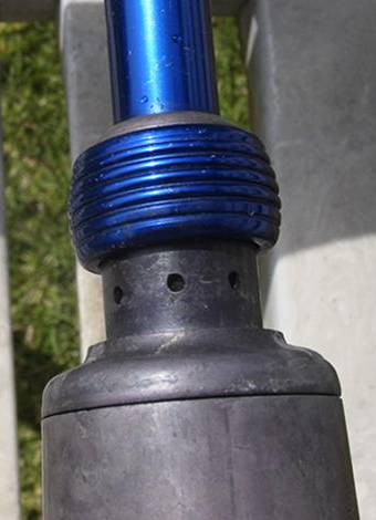
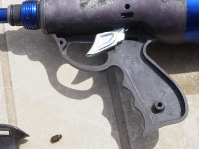
There are two "O" rings, I pushed the blue collar completely forwards onto the
barrel tube and could see the "O" rings at each end located underneath. The
circumferential groove in the front of the barrel base casting is to allow the
front "O" ring of the sliding collar to stop there, but of course you can
continue pushing it so that the blue collar comes completely off the casting.
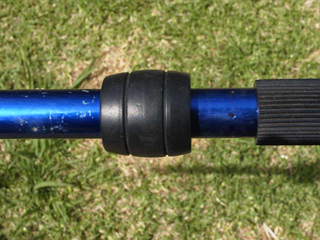
Although it is jammed I know that the blue tube with holes is actually the
handle of the hydropump, that entire outer tube section slides backwards on the
smooth inner aluminium tube which is the actual body of the hydropump. The
holes in the blue tubular handle are to stop water caught between the interior
of the handle tube and the exterior of the inner body of the pump being also
pumped, this would make the hydropump hard to operate as water would be pumped
both inside the pump body and outside it. The holes in the blue handle tube are
therefore simple vents to allow water to escape. The black rubber knob on the
rear of the hydropump is just a cover for the rear end of the sliding blue
handle tube.
If you are referring to the black rubber knob it just pushes onto the rear of
the vented blue tube which is the actual handle of the hydropump. The rubber
knob is simply something to push against with your hand, if you pulled firmly on
the knob then it would just pull off the rear end of the blue tube, the rubber
knob is only a press fit.
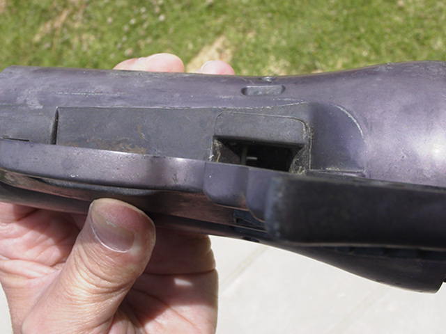
The hydropump is screwed into the centre section of the gun, you can see the
stainless steel receiver for the hydropump in photo 21 (at the top) and in photo
25 (on extreme right). A felt type seal provides the sealing when the hydropump
is screwed into place, there is little of this seal left, but it originally was
impregnated with grease. The hydropump was always easy to remove and should
have been pumped through with fresh water after removal from the gun at the end
of each day's diving. Unfortunately a previous owner of the gun did not do
this!
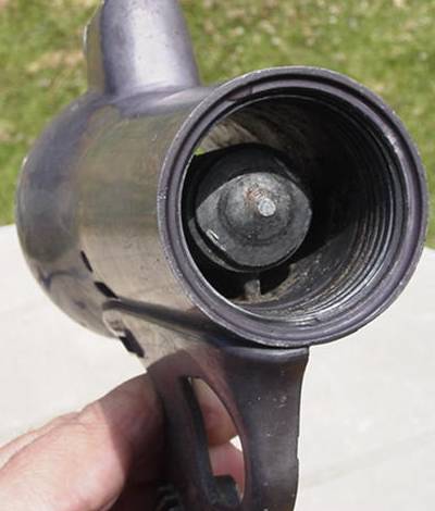
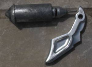
The dimensions I have shown on the attached document. Front cylinder with
conical top (firing valve) seals on the inner mouth of the barrel, it presses on
the large rubber cone shaped seat seen in photo 29, outer diameter of this
rubber valve seat is 23 mm.
The ring of holes at the front end of the barrel is to allow easy insertion
of the spear tail without having to overcome any resistance from the stored
air pressure in the gun. Water behind the spear tail will just flow out
through these small holes as the spear tail is first pushed into the muzzle.
There will be no loading effort until the spear tail's rubber cup seal
passes beyond this first ring of holes. Once the shaft has been fully
loaded in the gun then the rubber component on the barrel shaped like a
olive can be slid back to cover the holes and thus seal the barrel against
any more water escaping through these holes, either for the shot or for any
subsequent pumping action of the spear within the barrel. The spear can
function as a water pump rod as when pulled forwards in the barrel the cup
seal on the spear tail collapses allowing water to flow past it and into the
gun. Another way to allow the spear tail to be inserted would be to
simultaneously pull the trigger during the first few centimetres of spear
travel into the gun and then release the trigger, however the "Hydra" is too
long for this to be carried out by a single operator.
By pressing a trigger hook, the right valve has very small course. The
throttling effect arises because of a small crack between the left valve and the
cylinder of the trigger mechanism. I think, that the right valve is not
necessary.
The trigger valve body fits inside the rear bored out section of the firing valve body in order to provide a sliding connection that is biased in opposing directions
by the long coil spring trapped within these two components. When the gun is charged up to shoot these two valves, under the influence of the elevated hydrostatic
pressure inside the gun, press firmly on their respective valve seats at each end of the hydraulic locking chamber which is situated in the centre section of the gun.
The hydraulic lock condition prevents the gun from firing and is only released by moving the trigger valve inwards against the elevated hydrostatic pressure.
This action opens up the rear end of the hydraulic locking chamber which results in an instantaneous internal pressure drop back to ambient pressure within
the confines of the chamber. As the hydraulic locking chamber has a larger bore diameter (to accommodate the tubular rear section of the firing valve body)
than the bore diameter of the barrel which is situated immediately in front of it and both these sections are now at ambient pressure, then the firing valve body
is moved rearwards on the trigger valve body by the still elevated hydrostatic pressure within the main body of the gun, thus unplugging the rear of the barrel
and allowing water to escape and drive the spear from the gun.
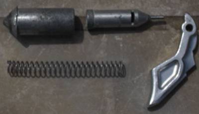
Both sections of this combined firing and trigger valve assembly are necessary.
The forward valve (left hand on photo) is the "firing valve", the rear valve
(right hand on photo) is the "trigger valve". The trigger valve slides inside
the firing valve with a small clearance between their contacting diameters in
order to prevent water flowing from the main pressure chamber out through the
trigger valve's exit port during the shot, hence the majority of water flows
down the barrel when the gun is fired. The small clearances between firing
valve and trigger valve components (refer to my diagram) serve as a transfer
port; unlike Aquatech gun there is no transfer port in "Hydra" gun as there are
no "O" rings on the firing valve's rear body. It also has no side ports,
contrary to what was said in that article by A. Yurchevskiy, only side ports (2
slots) are in rear end of trigger valve.
Note that the trigger valve in an Aquatech speargun was originally a downstream valve at the end of a small bore transfer pipe;
in the Alcedo "Hydra" the trigger valve is an upstream valve. Small rectangular vents (2 vertical slots mentioned above) in the rear end of the “Hydra” trigger valve body
are to assist water outflow from the telescoping interior volume as the trigger valve body slides forwards inside the firing valve body, even though water can escape along the small clearance between
the internal bore of the tubular firing valve body and the enlarged nose end of the trigger valve body. Note that the outer diameter of the rest of the trigger valve body
is reduced in order to limit the amount of sliding contact between the two valve bodies. The trigger valve body seals at its rear end on a nylon or delrin bush inset into
the cast centre section of the grip that forms the rear wall of the hydraulic locking chamber. In photo 24 you can see the stainless steel tail pin of the trigger valve
poking through this nylon bush, I have removed the cast trigger and pivot pin for these close-up photos. The nylon bush has a conical seat cut into it that matches the rear
conical taper on the trigger valve body, the actual contact area is right near the base, close to the rear pin in order to minimise the diameter of the trigger valve seat
and hence the force to be overcome when pulling the trigger.